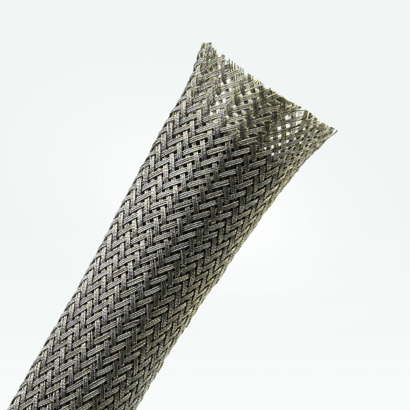
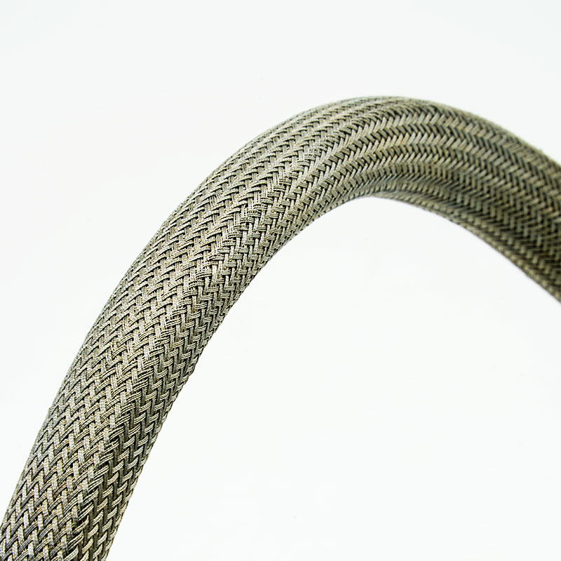
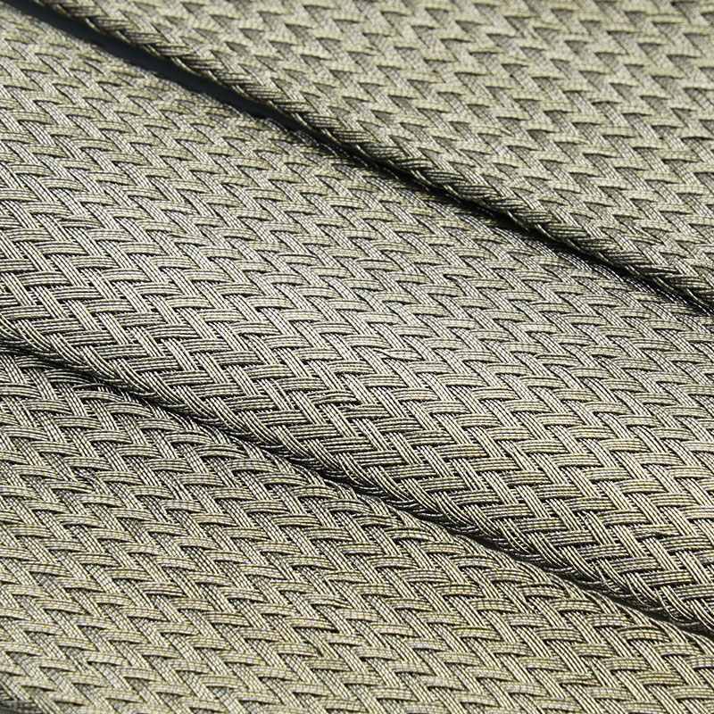
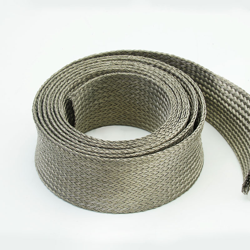
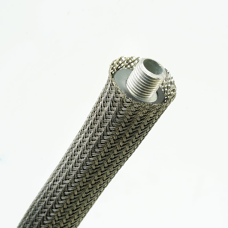
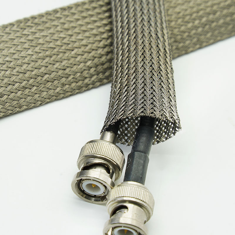
Why Choose MBS-CFW Copper Foil Braided Sleeving?
• Reduce shielding weight and bulk
Foil-based conductive filaments create a lightweight braid for compact electronic assemblies and mobile equipment.
• Protect delicate signal wiring
The flexible sleeve adds conductive coverage without the stiffness of a heavy metal-wire braid.
• Route through confined spaces
Expandable construction follows bends and changing bundle profiles in densely packed equipment.
• Support retrofit EMC improvements
The sleeve can be installed over accessible cable assemblies and connected to a suitable grounding system.
1. Conductive copper foil filaments
Provides a lightweight metallic shielding structure.
2. Low-bulk braided construction
Suitable for assemblies where weight and routing space are limited.
3. Expandable cable fit
Accommodates a defined range of cable and harness diameters.
4. Flexible handling
Follows curved routes and moving or serviceable cable groups.
5. EMI and RFI shielding support
Helps control radiated interference when correctly terminated.
6. Cable-bundle organization
Combines multiple wires under one conductive protective layer.
7. Application-specific customization
Diameter, braid density, filament construction, length and packaging can be reviewed.
| Material |
Tinned Copper Foil & Nylon Multifilament |
| Construction |
Expandable lightweight braid |
| Shield coverage |
Project-specific braid coverage |
| Standard appearance |
Metallic copper tone |
| Working Temperature |
-40℃~+125℃ |
| Flammability |
Self-extinguishing |
| Shielding Effectiveness |
≥75 dB (30 MHz-3GHz) per GB/T 30142-2013. |
| Standard Color |
Tinned Copper |
| Compliance documentatio |
RoHS, REACH |
| Cutting Tool |
Scissor |
Specifications
|
Part No
|
Flat Width(W)
|
Expanded Range(mm)
|
Packing
Length
(m/spool)
|
|
Inch
|
mm
|
Min.(I)
|
Max.(O)
|
|
MBS-CFW-004-TC
|
1/8”
|
4 |
3 |
7 |
250 |
|
MBS-CFW-006-TC
|
1/4”
|
6 |
4 |
9 |
200 |
|
MBS-CFW-008-TC
|
5/16”
|
8 |
6 |
12 |
150 |
|
MBS-CFW-010-TC
|
3/8”
|
10 |
7 |
16 |
150 |
|
MBS-CFW-012-TC
|
1/2”
|
12 |
8 |
20 |
150 |
|
MBS-CFW-015-TC
|
5/8”
|
15 |
10 |
23 |
100 |
|
MBS-CFW-020-TC
|
3/4”
|
20 |
13 |
28 |
50 |
|
|
1”
|
25 |
18 |
32 |
50 |
|
|
1-1/4”
|
30 |
30 |
50 |
50 |
|
|
1-1/2”
|
40 |
30 |
60 |
25 |
|
|
2”
|
50 |
40 |
60 |
25 |
● Note: Expanded range describes geometric capability, not the preferred continuous operating point. Selecting near maximum expansion increases braid openings, reduces surface coverage and shortens installed length.
Typical Applications
Electronic instruments and test equipment
Protects low-level signal cables where added metal weight and stiffness should be minimized.
Communication and data interconnects
Adds conductive coverage around compact signal bundles in space-constrained enclosures.
Robotics and lightweight automation
Shields moving control and feedback wiring while preserving cable flexibility.
Aerospace and mobile equipment prototypes
Supports weight-conscious harness development subject to project-specific material and compliance review.
Medical and laboratory equipment
Helps separate sensitive signal wiring from nearby electrical noise sources; final equipment compliance remains required.
Start with the cable diameter range, maximum allowable weight and bulk, required flexibility, frequency range and target assembly performance. Confirm installed braid coverage, grounding method, connector or enclosure interface, flex cycles and environmental exposure. Copper foil braid is selected mainly for lightweight flexibility; applications needing high grounding current, very low resistance or maximum mechanical robustness may be better served by MBS-TC.
Customization Available
Size and coverage - Braid diameter and density matched to the installed cable bundle
Filament construction - Foil filament type and supporting yarn structure can be evaluated.
Cut lengths and assemblies - Project lengths and selected termination preparation available by agreement.
Identification and packaging - Labels, reels, bags, kits and private-label packaging can be customized.
RoHS, REACH or other material documentation may be available for the confirmed construction. Shielding effectiveness and resistance must be stated only against an agreed method and sample configuration. The product does not by itself certify the cable assembly for EMC, aerospace, medical or other regulated use. Compatibility with soldering, crimping and environmental exposure must be confirmed.
Conductive filament verification - Foil filament identity, appearance and incoming condition are checked.
Braid quality control - Coverage, expansion, broken filaments and surface consistency are inspected.
Weight and dimensional checks - Nominal size, length and agreed mass parameters are verified.
Functional release inspection - Continuity or resistance checks can be specified together with final label and packaging review.
Frequently Asked Questions
01. How does copper foil braid differ from tinned copper wire braid?
Copper foil construction is generally lighter and more flexible; tinned copper wire braid is usually preferred for robust bonding, termination and higher current paths.
02. Can this sleeve be soldered directly?
It depends on the foil-filament construction and coating. Confirm the intended termination process before selection.
03.Will expansion reduce shielding coverage?
Yes. As a braid expands over a larger diameter, its coverage angle and optical coverage can change.
Request a Sample or Quote
Send the cable diameter range, installed coverage target, frequency range, grounding method, environment, finished length and annual quantity. MJ FLEX will review the shielding construction and recommend a sample or quotation configuration.




 English