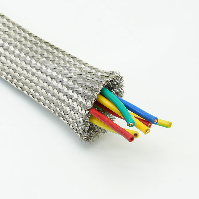
Why Choose MBS-TC Tinned Copper Braided Sleeving?
• Control electromagnetic interference
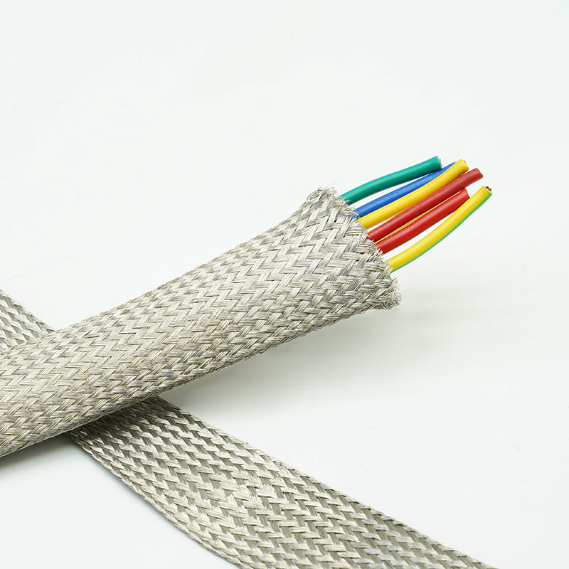
The conductive braid helps reduce radiated interference entering or leaving a cable assembly when correctly grounded and terminated.
• Create a low-resistance grounding path
Metal braid supports shield bonding between cable sections, connectors and grounded enclosures.
• Protect copper in demanding environments
Tin plating provides better surface oxidation resistance than bare copper and supports dependable termination.
• Shield irregular cable routes
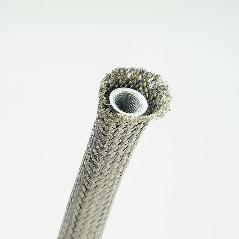
Expandable braid follows bends and diameter changes more easily than rigid metallic conduit.
1. Tinned copper wire construction
Combines copper conductivity with a protective tin-plated surface.
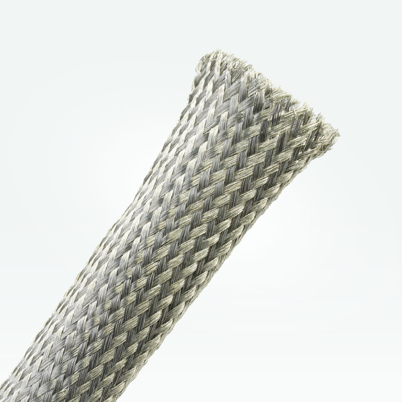
2. Expandable braided structure
Fits a defined range of cable and harness diameters.
3. EMI and RFI shielding layer
Provides conductive coverage for interference-control designs.
4. Flexible routing performance
Conforms to bends, branches and irregular harness profiles.
5. Grounding and bonding capability
Supports conductive termination to backshells, clamps or grounded housings.
6. Solderable termination surface
Tin plating facilitates common soldering and connection processes.
7. Custom braid configurations
Wire diameter, coverage, size, length and packaging can be reviewed for OEM projects.
| Material |
Tinned copper wire |
| Construction |
Expandable metal braid |
| Shield coverage |
Project-specific braid coverage |
| Working Temperature |
-40℃~+150℃ |
| Melting Point |
1084±5℃ |
| Shielding Effectiveness |
≥75 dB (30 MHz-3GHz) per GB/T 30142-2013. |
| Standard Color |
Tinned Copper |
| Compliance documentatio |
RoHS, REACH |
| Cutting Tool |
Scissor |
Specifications
|
Part No
|
Flat Width(W)
|
Expanded Range(mm)
|
Packing
Length
(m/spool)
|
|
Inch
|
mm
|
Min.(I)
|
Max.(O)
|
|
MBS-TC-003-TC
|
1/8”
|
3±1 |
1 |
4 |
250 |
|
MBS-TC-006-TC
|
1/4”
|
6±1 |
5 |
8 |
200 |
|
MBS-TC-008-TC
|
5/16”
|
8±2 |
6 |
12 |
200 |
|
MBS-TC-010-TC
|
3/8”
|
10±2 |
7 |
17 |
150 |
|
MBS-TC-012-TC
|
1/2”
|
12±2 |
8 |
20 |
100 |
|
MBS-TC-016-TC
|
5/8”
|
16±2 |
10 |
23 |
100 |
|
MBS-TC-020-TC
|
3/4”
|
20±2 |
13 |
26 |
50 |
|
|
1”
|
25±2 |
18 |
33 |
50 |
|
|
1-1/4”
|
32±2 |
20 |
50 |
50 |
|
|
1-1/2”
|
38±2 |
30 |
60 |
50 |
|
|
1-3/4”
|
45±2 |
35 |
75 |
25 |
|
|
2”
|
50±2 |
40 |
80 |
25 |
● Note: Expanded range describes geometric capability, not the preferred continuous operating point. Selecting near maximum expansion increases braid openings, reduces surface coverage and shortens installed length.
Typical Applications
Industrial control and automation cables
Reduces interference around motor drives, sensors and control signals while supporting enclosure bonding.
Automotive and EV electrical systems
Adds flexible shielding around low-voltage signal, communication and auxiliary harnesses near electrical noise sources.
Robotics and servo systems
Protects feedback and control cables routed close to motors, drives and switching equipment.
Communication and data equipment
Helps control radiated noise on interconnects that require conductive shield continuity.
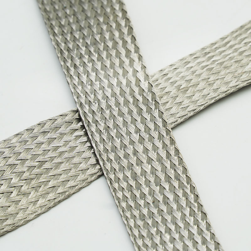
Ground straps and bonding assemblies
Provides a flexible conductive braid for custom grounding links and enclosure connections.
Define the cable diameter range, required installed braid coverage, frequency range and target system-level shielding performance. Also specify bend and flex conditions, current or bonding requirement, environment, termination method and connector geometry. Shielding results depend on the complete assembly, especially coverage, seams, grounding and 360-degree termination; the sleeve alone does not determine final EMC performance.
Customization Available
Nominal diameter and expansion - Sized for the actual cable, connector and installed coverage requirement.
Wire and braid construction - Wire diameter, carrier count and braid density can be evaluated.
Finished lengths - Cut pieces or fabricated assemblies available after drawing review.
Termination and packaging support - Options may include crimping, soldering, labels, reels, kits and OEM packaging.
Material declarations such as RoHS and REACH may be available for the confirmed construction. Shielding effectiveness, DC resistance, current capacity, corrosion performance and temperature limits must be based on agreed test methods and the exact supplied configuration. Final EMC compliance must be verified on the customer cable assembly or equipment.
Material identity control - Copper wire and tin-plated surface are checked against the approved specification.
Braid construction inspection - Wire condition, picks, coverage consistency and broken strands are monitored.
Dimensional verification - Nominal size, expansion and finished length are checked.
Electrical and release checks - Resistance or continuity testing can be agreed, followed by label and packing verification.
Frequently Asked Questions
01. How should the sleeve be grounded?
Use a low-impedance termination appropriate to the frequency range, ideally with circumferential contact to the connector or enclosure.
02. Does the sleeve have a fixed shielding effectiveness value?
Not universally. Performance changes with braid coverage, installed diameter, frequency and termination quality.
03.Why use tinned copper instead of bare copper?
Tin plating improves surface oxidation resistance and solderability while retaining copper-based conductivity.
Request a Sample or Quote
Send the cable diameter range, installed coverage target, frequency range, grounding method, environment, finished length and annual quantity. MJ FLEX will review the shielding construction and recommend a sample or quotation configuration.




 English